Cisco® 350-601 Exam (page: 14)
Cisco® Implementing and Operating Data Center Core Technologies (DCCOR)
Updated on: 01-Sep-2025

Viewing Page 14 of 106

DRAG DROP (Drag and Drop is not supported)
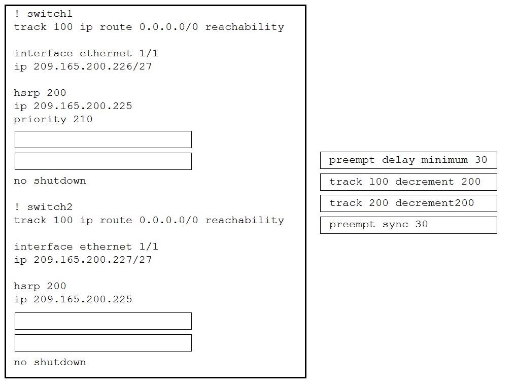
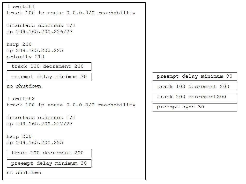
An engineer must configure the HSRP protocol to implement redundancy using two Cisco Nexus Series Switches, in addition, me HSRP must meet these requirements:
* switch1 must retain the primary role if switch2 goes offline.
* switch1 must retain the primary role until normal conditions are restored.
* switch1 and switch2 must ensure that the routing tables are converged before taking the active role.
* switch2 must retain the primary role if the default gateway is not reachable.
Drag and drop the configuration commands from the right to the left to meet the requirements. The commands are used more than once. Not all commands are used.
Select and Place:
  1. See Explanation section for answer.

Answer(s): A

Explanation:


Refer to the exhibit. During a vPC peer switch reload, there is packet loss between the server and the router. Which action must be taken to prevent this behavior during future reloads?

  1. Set the routed uplink ports of the Cisco Nexus peers as orphans.
  2. Increase the vPC delay restore timer.
  3. Disable vPC ARP synchronize on the vPC peers.
  4. Decrease the OSPF hello and dead interval timers.

Answer(s): B

Explanation:

After a vPC peer device reloads and comes back up, the routing protocol needs time to reconverge. The recovering vPCs leg may black-hole routed traffic from access to aggregation/core until uplink Layer 3 connectivity is re-established. vPC Delay Restore feature delays vPCs leg bring-up on the recovering vPC peer device. vPC Delay Restore allows for Layer 3 routing protocols to converge before allowing any traffic on vPC leg. This results in a more graceful restoration and zero packet loss during the recovery phase (traffic still gets diverted on the alive vPC peer device). This feature is enabled by default with a vPC restoration default timer of 30 seconds. The timer can be tuned according to a specific Layer
3 convergence baseline from 1 to 3600 seconds.


Reference:

https://www.cisco.com/c/en/us/support/docs/ios-nx-os-software/nx-os-software/212589-understanding-vpc-election-process.html


A Cisco ACI engineer must configure an access port on a Cisco ACI leaf switch. The access policy should be configured so that it supports L3Out connectivity concurrently with several EPGs that are mapped to this interface with the static port method. How should the access policy be configured?

  1. by linking the interface policy group to multiple Attachable Access Entity Profiles
  2. with two interface policy groups that are linked to the same interface profile port selector
  3. by mapping a single physical domain, mapped to the L3out and EPG interfaces
  4. with a single Attachable Access Entity Profile that is linked to the corresponding routed domain and physical domain

Answer(s): D

Explanation:

The access policy (the interface policy group) needs to have one single Attachable Access Entity Profile assigned since it is the same interface. Then different physical domains can be used for the routed and switched domain.


Refer to the exhibit. An engineer monitors ingress traffic from Host-A and all traffic for VLAN 20 from Host-B. Which configuration must be implemented to monitor and export traffic to Network Analyzer?

  1. SW-1(config)# monitor session 5 SW-1(config-monitor)# source interface ethernet 1/2 rx SW-1(config-monitor)# source interface ethernet 1/1 tx SW-1(config-monitor)# source vlan 20 both SW-1(config-monitor)# destination ip 10.10.10.1 SW-1(config-monitor)# no shut
  2. SW-1(config)# monitor session 5 type erspan-source SW-1(config-erspan-src)# source interface ethernet 1/2 rx SW-1(config-erspan-src)# source vlan 20 both SW-1(config-erspan-src)# destination ip 10.10.10.1 SW-1(config-erspan-src)# erspan-id 111 SW-1(config-erspan-src)# no shut
  3. SW-1(config)# monitor session 5 SW-1(config-monitor)# source interface ethernet 1/2 rx SW-1(config-monitor)# source interface ethernet 1/1 both SW-1(config-monitor)# source vlan 20 both SW-1(config-monitor)# destination interface ethernet 2/1 SW-1(config-monitor)# no shut
  4. SW-1(config)# monitor session 5 type erspan SW-1(config-erspan-src)# source interface ethernet 1/2 rx SW-1(config-erspan-src)# source interface ethernet 1/1 both SW-1(config-erspan-src)# destination ip 10.10.10.1 SW-1(config-erspan-src)# mtu 1000 SW-1(config-erspan-src)# no shut

Answer(s): B

Explanation:


Reference:

https://www.cisco.com/c/en/us/td/docs/switches/datacenter/nexus5600/sw/system_management/7x/b_5600_System_Mgmt_Config_7x/ b_6k_System_Mgmt_Config_7x_chapter_01110.html


Refer to the exhibit. Which action completes the vPC domain implementation?

  1. Add the vPC member ports to the vPC channel group.
  2. Configure the system MAC on the vPC domain.
  3. Include the VRF management on the vPC domain.
  4. Allow VLANs on the vPC peer link member interfaces.

Answer(s): A

Explanation:

The physical interfaces need to be added to the Portchannel group. Configuring allowed VLANs on the vPC peer-link is optional.


Viewing Page 14 of 106


Share your comments for Cisco® 350-601 exam with other users:

Finn 5/4/2023 10:21:00 PM

i appreciated the mix of multiple-choice and short answer questions. i passed my exam this morning.
IRLAND